
Tech Art Chronicles: SDFS - Part Two
Distance Fields
There is no S in SDF without the Distance Fields!In the PART1 of SDF tutorial I covered texture distance fields and how they mostly aren’t “signed” because they aren’t negative values without re-mapping some ranges. That makes sense and the effects still you can make some amazing things with textures like this:
That’s cool but how do I get the crazy math generated signed distance fields and not need to use textures to make our distance fields at all? Without textures, math SDFs can do amazing gradients/crazy animations/add/mask:
The examples below will work in Unreal and Unity and I will try to show off both of the engines. I also will reference Adobe products but none of these are necessary to understand the concepts below.
Math Signed Distance Fields
Let’s start with a basic circle
Signed Distance Fields as textures are quite useful and do cool things but perhaps the more interesting concept with SDFs is replacing textures with pure math instead! Say for instance you wanted to have a nice circle background for some icon. The classic approach might be to make a circle in an image editor like Photoshop, save it out as a texture, import that texture into the engine, and place it under the icon. However, there is a way to use MATH to generate the circle instead. The benefits of creating SDF visuals in engine include the flexibility to change size/gradient/animations/strokes and much more. So let’s start that circle example.
In terms of all things SDF, I head over to IQ’s website as it’s an amazing resource for SDFs that include the equations to make all kinds of shapes. But for the example sake say I wanted to generate a circle, that’s pretty easy if you look at IQ’s 2D primitives and the first shape is a circle:
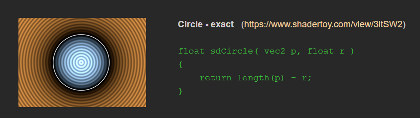
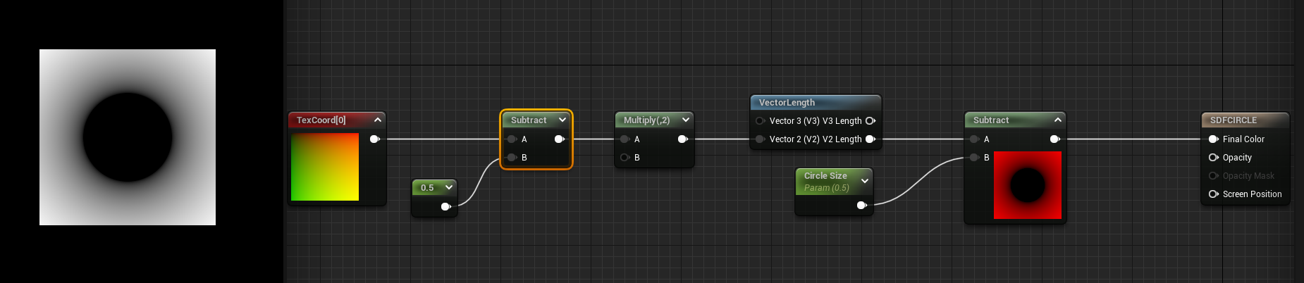
Now to translate this equation into Unreal or Unity, you don’t even need to make a custom HLSL node though I’ll go over that later. With an equation this simple I just need to take the length of the UV in IQ’s equation the UVs are always called vec2 p and subtract it by the size of our circle r.
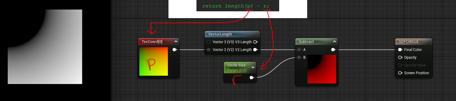
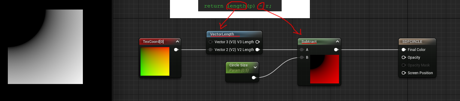
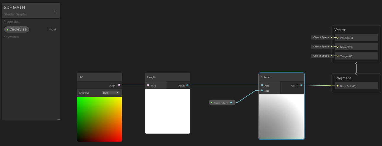
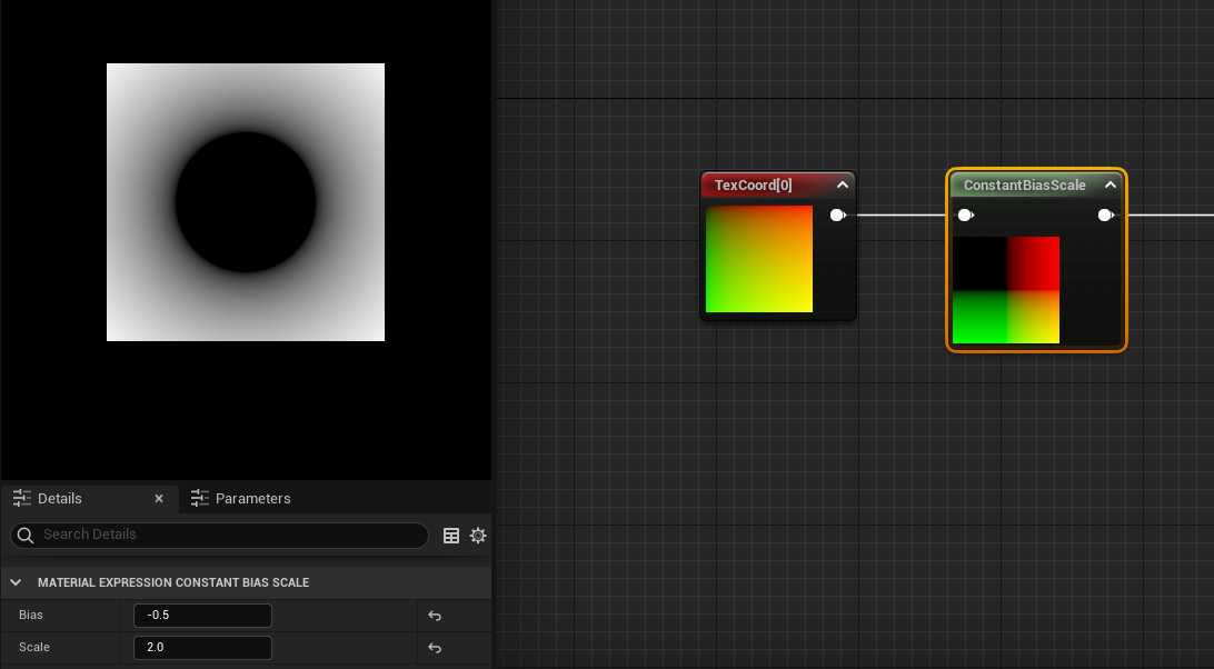
I took that equation from IQ and broke it into nodes in Unreal. P is the TexCoord[0] then take the length and subtract a parameter I’m calling Circle Size and that makes me a circle.
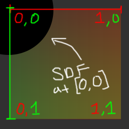
BUT there’s something wrong, the circle is actually in the top left corner and not in the center of the material. That’s because the coordinate system is in the wrong range. I’ll draw a really crude diagram to demonstrate this:
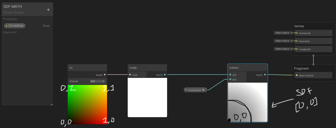
The X axis on this diagram here represents is the RED channel and Y axis is the GREEN channel. So based on this graph the SDF is drawing it’s center at [0,0] and drawing it’s radius at .5 (our circle size) from the center. NOW for fun we can look at Unity here and you can see Unity has the Y coordinate flipped so it’s always drawing [0,0] in the bottom left:
So Unity draws the circle SDF a little bit different, it’s actually showing it in the bottom left and not the top left like Unreal. Because if you look at the UV coordinates they have the Y-axis start at the bottom as 0, rather than Unreal which has 0 start at the top of the coordinates.
Regardless of the engine I need to get the coordinate system to center [0,0] to be in the middle of the material. To make this happen I need to actually scale the coordinates down and shift it over. Here’s a gif of what it’d be doing in the shader via Photoshop transforms:
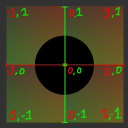
What I’ve essentially done in terms of the math is remapped the range to be from 0-1 to -1-1. To do this I am using a concept called the Constant Bias Scale and to see that graph here’s what it is:
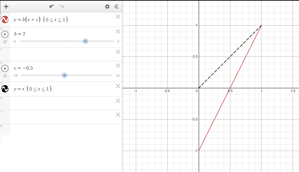
Using this graph here you can see if I want the range to go from 0-1 to -1-1 I just need to subtract .5 and multiply by 2. But why these random numbers?
To remap the range if I just multiplied by 2 it would go from 0-2 so to offset scaling, first I need to subtract .5 as that will shift the range in the negative first -0.5-0.5 and then when you multiply .5 by 2 you get 1. Hopefully the visual gives a good idea of the math at work.
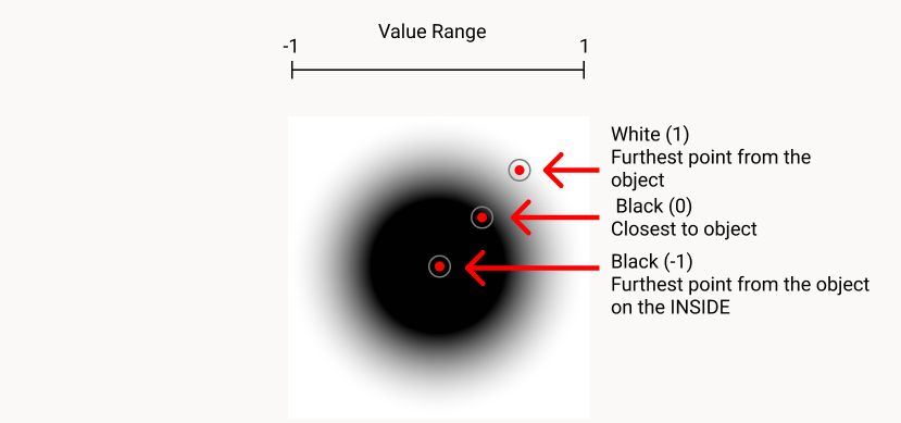
Because the ranges are between -1-1 the SDF should now have the true negative values to get the internal distance and external distance.[See previous tutorial for more on this concept]
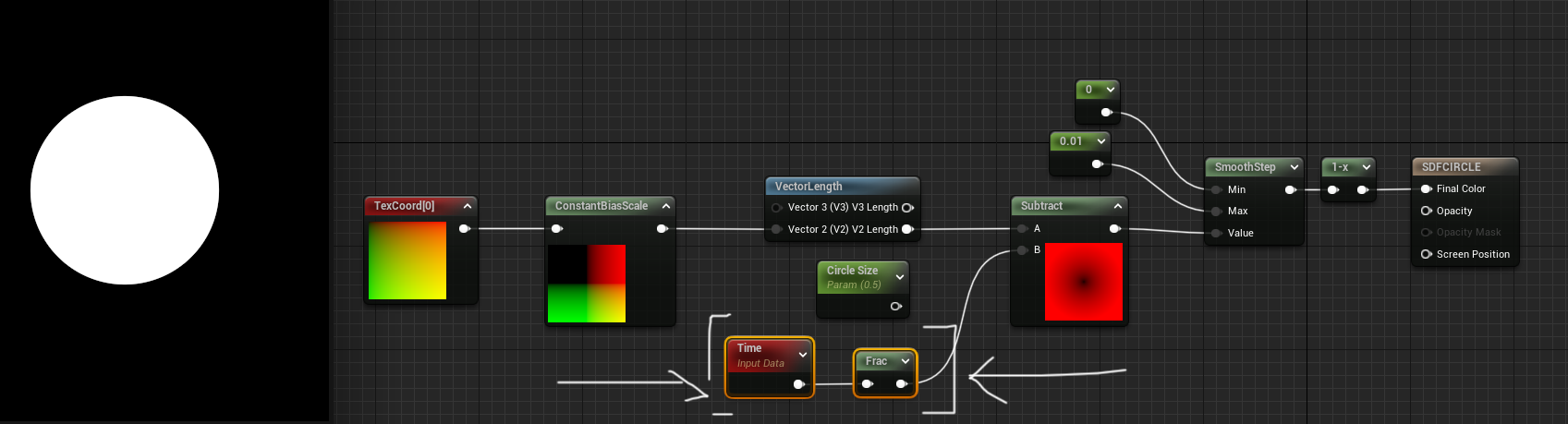
The Unreal graph now includes the new UV coordinate range that has the subtract node and multiply node that go BEFORE the length calculations:
And this is that same UV coordinate range remaped in the Unity graph:
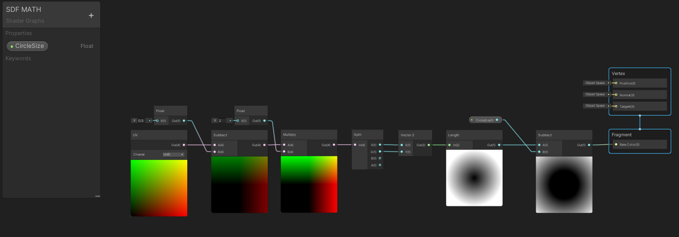
Unity is a bit more picky as it wants the UV to be a vector2 for this calculation. I solved this by splitting the vector4 into a vector2. Sadly I needed to do this to for this part of the tutorial but this step isn’t needed later with custom HLSL shapes. So just note I did this for the circle demonstration but shouldn’t be necessary when using custom code nodes.
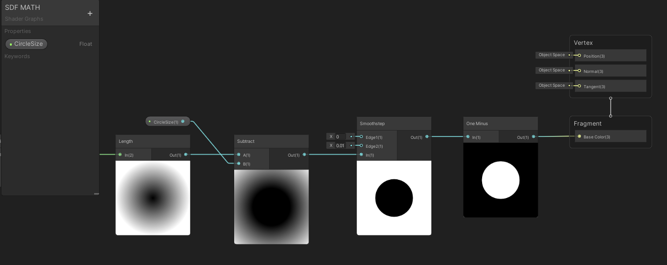
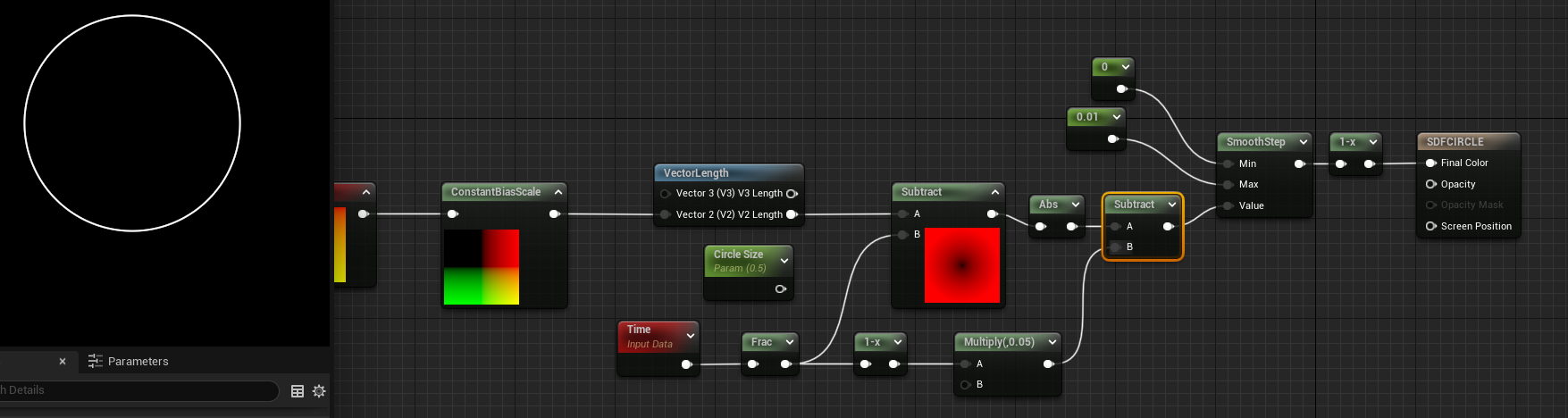
GREAT now I’ve got myself a math SDF circle... what can I do with it? Like a texture distance field I can make it feathered or less feathered and that’s pretty basic but let’s add that in so I can solidify the circle to be less feathered by adding a smoothstep node and inversing the colors with the one minus node.
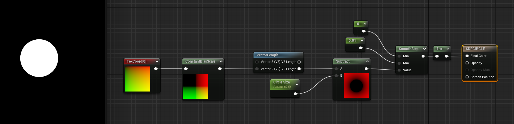
For Unreal engine, it’s same concept: Smoothstep node then invert the colors with a one minus node. My smoothstep values are Min: 0 and Max: 0.01
Now how about animating the size of the circle? That’s easy I made that little circle size at .5 so I can replace that with some time animation:
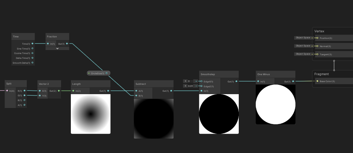
Sending time node through a frac node will reset the time to always animate between 0-1 and that’s perfect to scale up the circle from 0-1! Voila! Easy animation? Yes please!
And it’s exact same graph in Unreal.
But I can do more... I can convert the circle into a stroked circle easily with SDFs... and why not animate the stroke thickness?
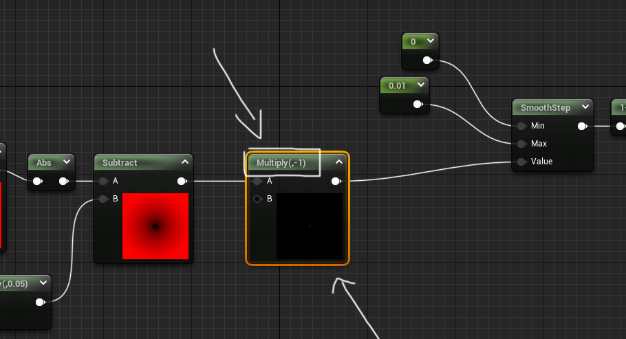
As a reminder from my previous SDF tutorial you can stroke any SDF with an absolute node then go into a subtract node and the number in the subtract is the thickness of the stroke:
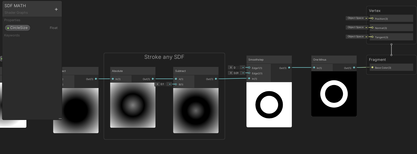
I got confused and almost plugged it into the smoothstep instead of the thickness of my stroke in the gif above. But as the circle gets larger the opposite is happening to the thickness of the stroke.
Here’s that same animation but in Unreal:
This material doesn’t use any textures, any extra animations, or layers, it's all simply done with some basic math... But this is where the fun starts... combining MULTIPLE SDF math shapes!
Math Signed Distance Fields - COMBINE, BLEND, AND MASK SHAPES
Just like vector graphics (kinda...) For the combining and masking of SDF shapes I’m going stick to just Unity for this section as their graph editor animates each node unlike Unreal by default. Those animations will hopefully help show what’s going on with the SDFs more clearly. However all of these nodes in the following section exist and are possible in Unreal so don’t worry it’s all the same until you get into custom HLSL but I’ll go over that.
COMBINING SDFS:
To combine SDF shapes I need to make myself another shape. So I’m going to add another circle to my little material here and this circle should animate across the material going from top to bottom. The Unity graph below shows how I animate the circle starting at the top of the material and animating down to the bottom.
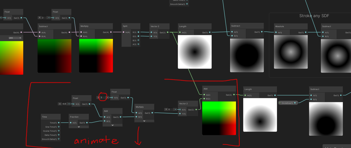
The little detail of this graph is that I changed the multiply to 3. This was to make sure the circle looks like it’s animating from outside the material -> into the material frame -> then outside of the frame cleanly. This sounds a bit complicated however in practice it’s quite easy to visually understand as it is an seamless scrolling circle from top to bottom:
Now I can demonstrate how to combine the static circle and the scrolling top to down circle. To do that I use the minimum node:
It’s essentially as if you were layering the static circle with the animating circle ontop of each other. Imagine the circles as Photoshop layers or After Effects layers ontop of each other that’s what a minimum node will do. From what I understand with my limited math it will do a quick branch to find the minimum values of these combined SDFs using that logic to combine them.
MASKING SDFS:
If I used a minimum node to combine SDFs it hopefully makes sense that the maximum node would be used to mask the SDFs. .
Taking a page from another IQ article on 3D SDFs this article has a union/subtraction/intersection section. While this article shows examples for 3D SDFs it also applies to 2D SDFs. So I will use these concepts to mask and intersect the SDF shapes.
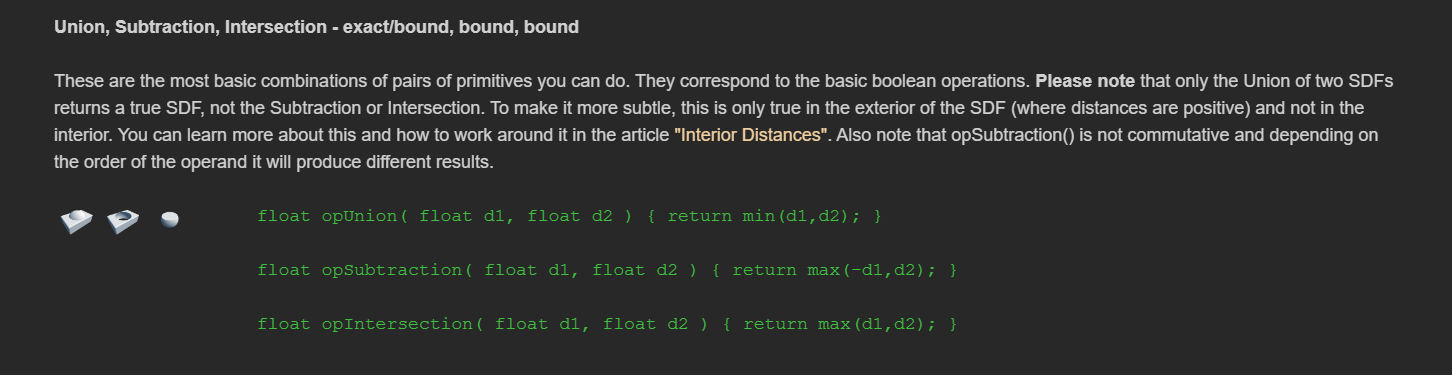

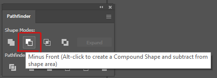
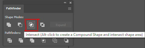
These are screen shots from Illustrator and it’s the pathfinder shape tools, Unite, Minus Front (subtraction), and Intersect. These are amazing icons to help show what the shapes are visually doing with our SDF combinations!
First let’s go into the Minus Front or subtraction! To do this I just need max(-d1,d2). I will put the SDF through a negate node (make it negative) that will be the SDF that will subtract from the second SDF in the maximum node:
Depending which shape you want to be in front subtracting from the shape under it is the shape you want to turn negative with the negate node. If I want the static circle to subtract the animating circle then you want the static circle to be the negative SDF. To make the animating circle to subtract from the static circle then you would turn the animating circle negative (with a negate node) and run it through the maximum node. What’s interesting is with the two circles here with the different subtraction method ontop make fun moon/eclipse animations. The static circle ontop subtracting from the animating circle kinda makes an eclipse - the shadow of the moon blocking out the sun - and the other subtraction looks like a moon phase where the moon is going through it’s whole moon cycles:

Fun to see which SDF is negative before putting them both in a maximum node changes the masking effect!
After that semi complicated setup for subtraction, the intersection is much easier. Intersection is just the maximum node between the two SDFs and you can see it only shows where they intersect:
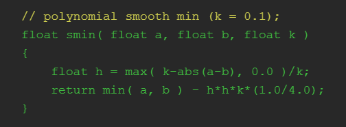
There’s also smooth union/subtraction/and intersection equations from IQ but I’m not going to quite go over that in this article. Instead I want to re-iterate just like the pathfinder tool in Illustrator you can unite/subtract/intersect your SDF shapes:
Unite: min(SDF1, SDF2)
Subtraction: max(-SDF1, SDF2)
Intersection: max(SDF1, SDF2)
Quick note Unreal doesn’t have a negate node that I know of, so just multiply your SDF by -1:
BLENDING SDFS:
Another fun thing to do is blend the two SDFs using a Linear Interpolate node, or Lerp for short, which will allow you to determine the weight of how much of each SDF will attempt to blend together. This makes the following results where the circle drop animation is now affecting the static circle to various degrees by changing the lerp between 0 (the static circle) and 1 (the falling circle) somewhere in the middle you can get this lovely teardrop animation.
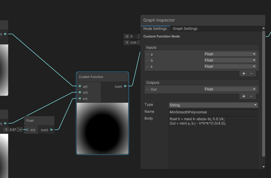
I’ll go into custom nodes a little bit later in this write up so do n’t worry about that part here. The results from the custom SmoothMinimum are quite different from the lerp blending but the blends are amazing:
IQ’s blend shows off the power of math SDF’s shapes vs textures. The visuals of combining these two distance fields can get that goopy delish middle area that would be very difficult to do with just textures. The blend works when the circles are close to each other they will almost merge into one circle and as they get further apart they into seperate circles. Unlike the lerp which is a weight between the two shapes of which shape is more dominant to show visually, this blend will actually work to merge the two shapes when they are close and separate them when apart. I can also choose how much blend to use, so in this gif above, a little blend keeps each circle their own distinct shape, more blend merges the circles into one big blob.
There’s also different equations for cubic and quadratic blends as well. I believe this blend is the easiest and gets the general results at a fairly cheap cost, so I figured that’s the one I would demo here. But if you feel inclined go see some of the other ways to blend and try them out.
NOW if I were to add back our stroke and grow the stroke over time with some of these blends/combine/subtract/intersect I can already get some amazing crazy animations with just messing around with a few of these nodes in combination:
Again these are just made from 2 circles with various ways to blend/combine/mask them together to make these different animations. The combinations of shapes and animations seem quite endless and this is but two circles... what if I do MORE shapes? Well let’s do it!
Making SDF Shapes
Convert GLSL into HLSL with custom nodesThis is where we begin to use the Custom HLSL node a lot more and I’ll show you what I mean. So for a circle the math was quite easy:
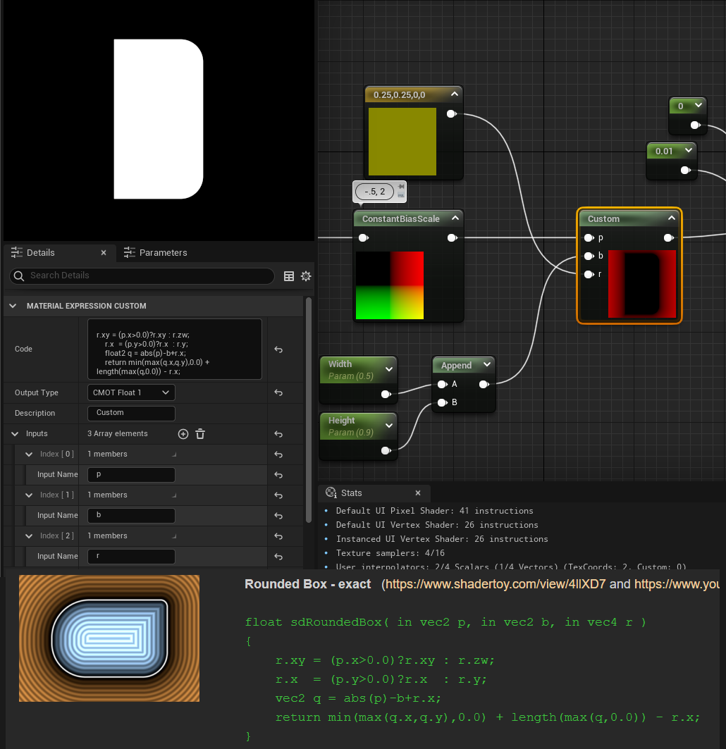
But when getting into more 2D SDF shapes it turns this simple length(p) - r into a bit more complex programming. Say for instance you want to do the triangle shape:
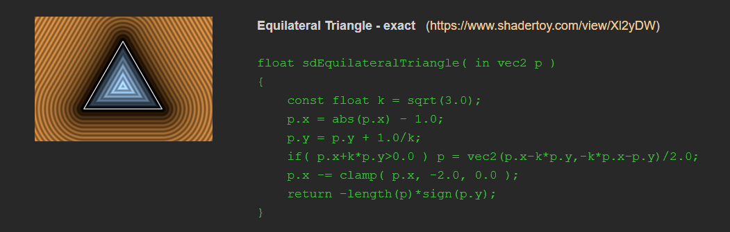
You could do with the nodes and recreate all of it... which I have done... but I do not recommend it! Instead you can often copy and paste this code in with a little bit of conversion into a custom HLSL node in unity and unreal to make all that math go away. I’ll show the steps I take to import custom SDFs into my graphs:
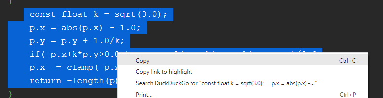
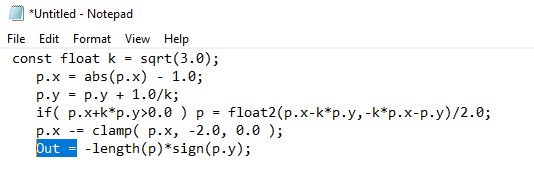
The first step I do is copy the text into some kind of notepad editor:
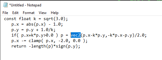
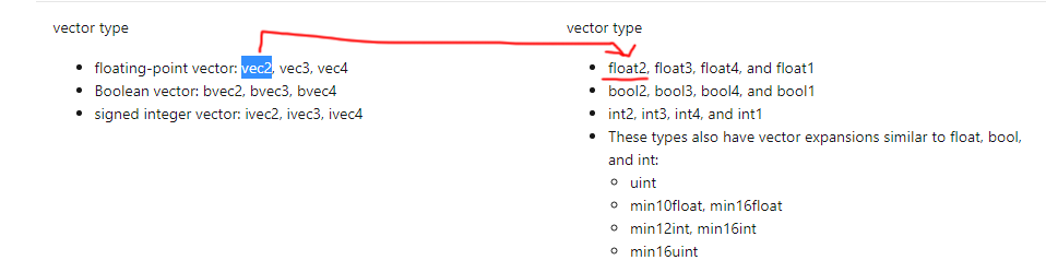
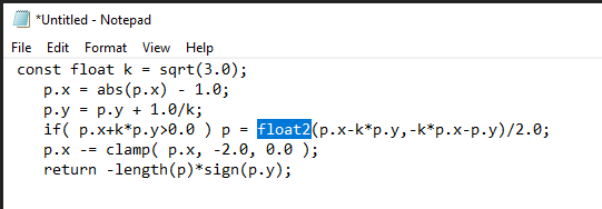
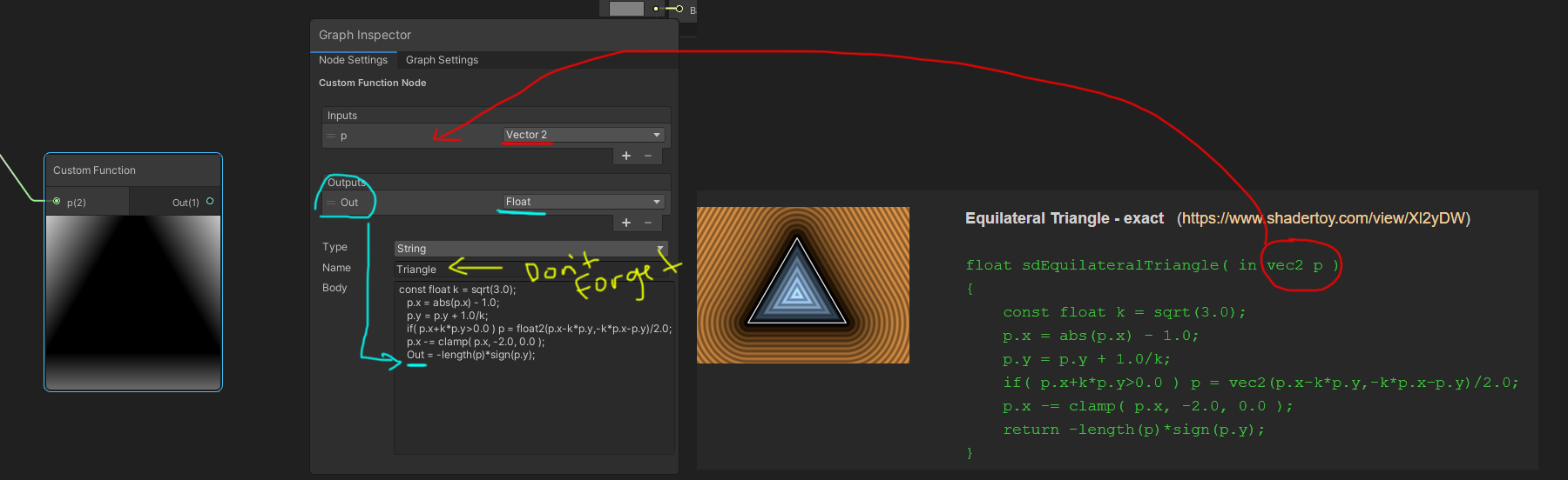
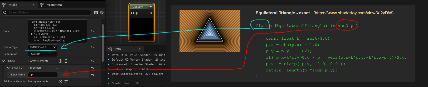
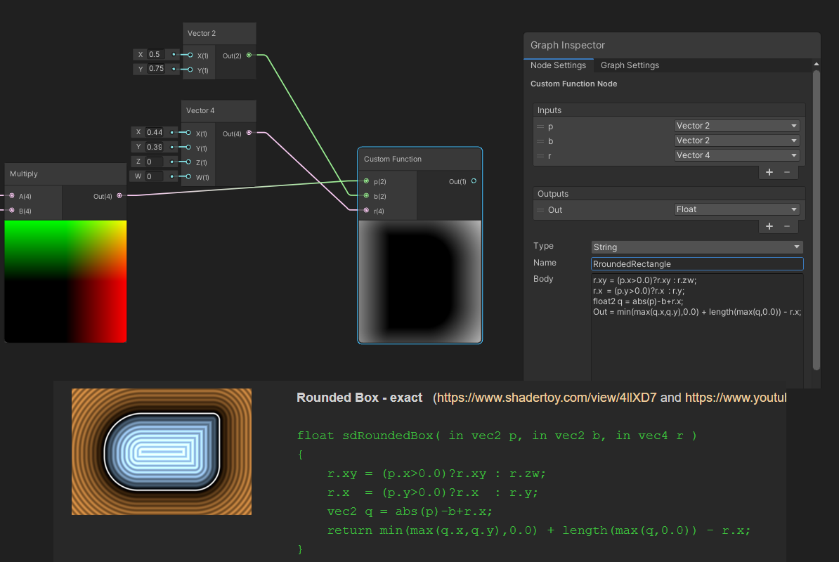
Then I need to convert everything that’s in GLSL to HLSL. Both GLSL and HLSL are shader coding languages and are quite similar. Game engines tend to use HLSL and shadertoy and some web applications use GLSL. IQ’s shapes are written in GLSL so I need to convert them to HLSL for Unity or Unreal. There’s a handy site I pull up if I find something that I don’t know how to convert from GLSL to HLSL via Microsoft. You can see here I need to change over the vec2 into a float2:
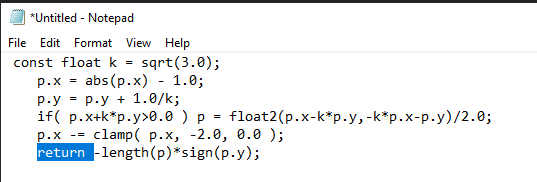
And if I’m using Unity I do a little extra work here by just changing the Return to Out =
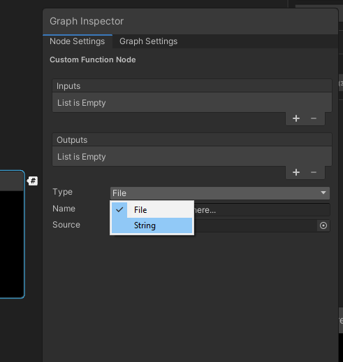
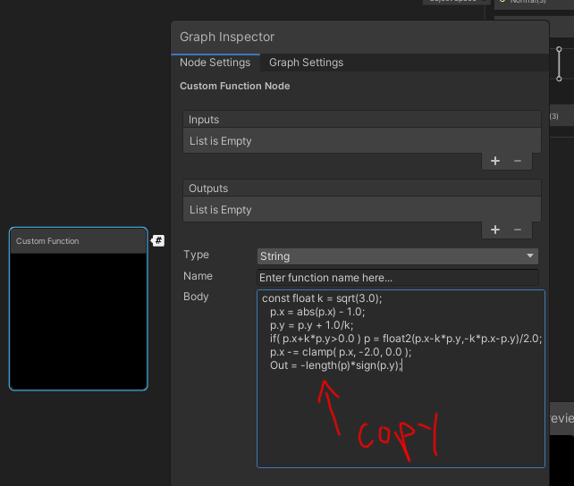
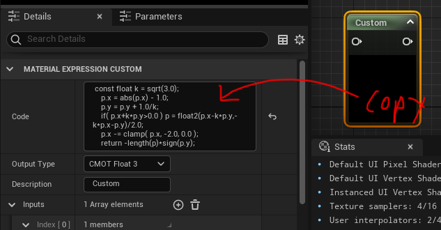
Great now I can make a custom function node in Unity or a custom node in Unreal:
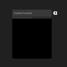
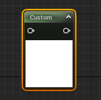
And copy the respective code into the right sections:
For Unreal:
Then you should be able to plug in the UV coordinate for p so make sure it’s the UV in the right coordinate space with the constant bias scale I showed off earlier. Then after your SDF run it through a smoothstep node at the end to sharpen it, one minus node to invert the colors, and voila I’ve got a triangle SDF:
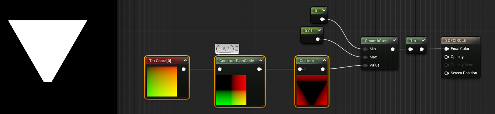
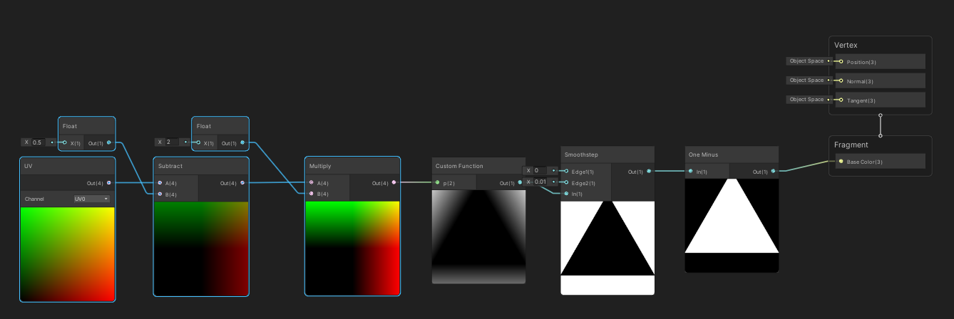
Multiply/Divide will scale the UV coordinates which inturn will scale the SDF down or up depending on the values. For instance if I multiplied by .5 it would scale the triangle to be larger but if I multiply by 2 like in the example gif it’s scaling the triangle down by half. I favor multiply over divide just because you can accidentally get divide by 0 which computers REALLY dislike so I tend to use multiply in most of my scaling UV adventures.
To do this in Unity and flip the triangle you can specify more easily in Unity what parts of the vector to multiply:
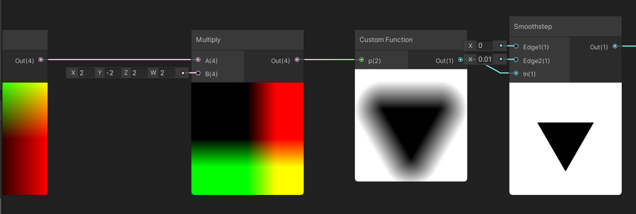
In this case I multiplied the Y by -2 to both scale by half and flip/mirror the triangle to point down and X by 2 to scale down the triangle by half.
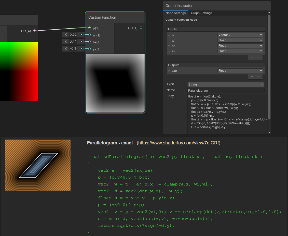
Lastly here’s just a few other custom HLSL nodes making a few other shapes so you can see the examples of converting a few other SDFs:
Now you can combine a bunch of SDFs together, stroke them, round the edges, and animate them to do crazy things. When I started to explore SDFs I was amazed at all the really great looking outcomes from just experimenting with the various methods to animate and combine them.
Here’s just a few random lerping animations with time and scale I played around with:
Enjoy the endless options for SDFs and maybe next time we’ll get into persudo randomly generating SDF patterns/time/and particle system like animations:

This is a terrible example but I had nothing else on the mind.