Tech Art Chronicles: No Textures
From Technically Speaking Discord Challenge
In the Technically Speaking Discord we had ourselves a fun weekly challenge to do a no-texture challenge. This is my jam. I'm quite the no-texture savant as I love to use SDFs and noise for everything. I also don’t like having to switch between photoshop and unreal/unity so avoiding textures is an easy way to stay in the engine and not mess up my workflow.
REFERENCE:
Lately I’ve been re-watching Neon Genesis Evangelion and I thought it’d be cool to try to reference/replicate the holographic map that’s weirdly projected in that show.
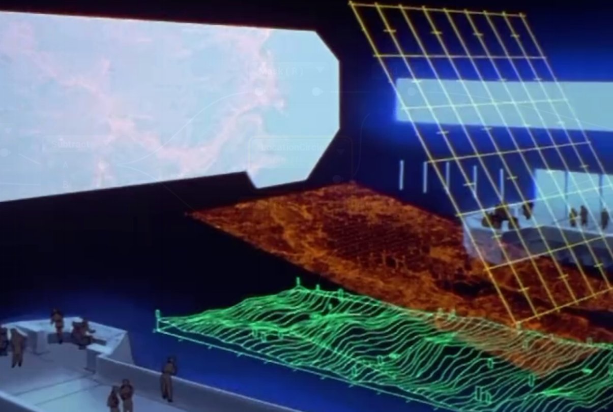
In the show the map has 3 layers:
First layer is the geography wiggle lines that look a bit like a topographic map
Second layer is the city/geography visualized
Third layer is some weird yellow grid
MAKE ME SOME NOISE:
The noise part was a bit dissapointing, I wanted to make FBM noise, but I couldn’t get the custom node HLSL loop to work with the noise I had set up previously. So I ended up using unreal’s noise nodes and some custom noise functions. Not ideal but I didn’t want to spend the entire challenge working on making noise, it’s what you do with the noise that counts.
I haven’t tried mapping noise to a render texture so that was exciting to try. I followed this unreal write up on that process.
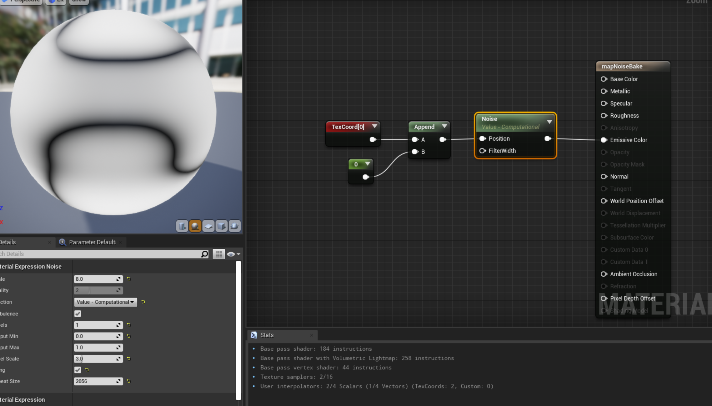
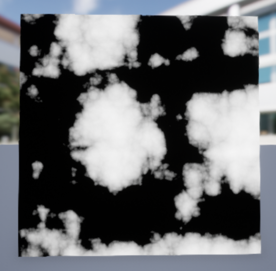
So I have my noise texture now but I need a little bit more.
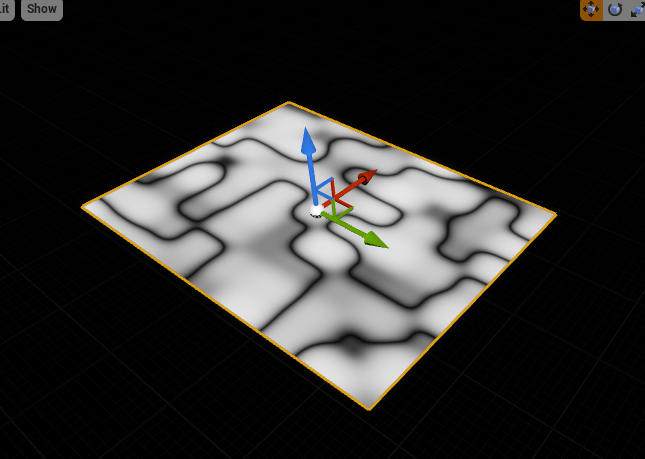
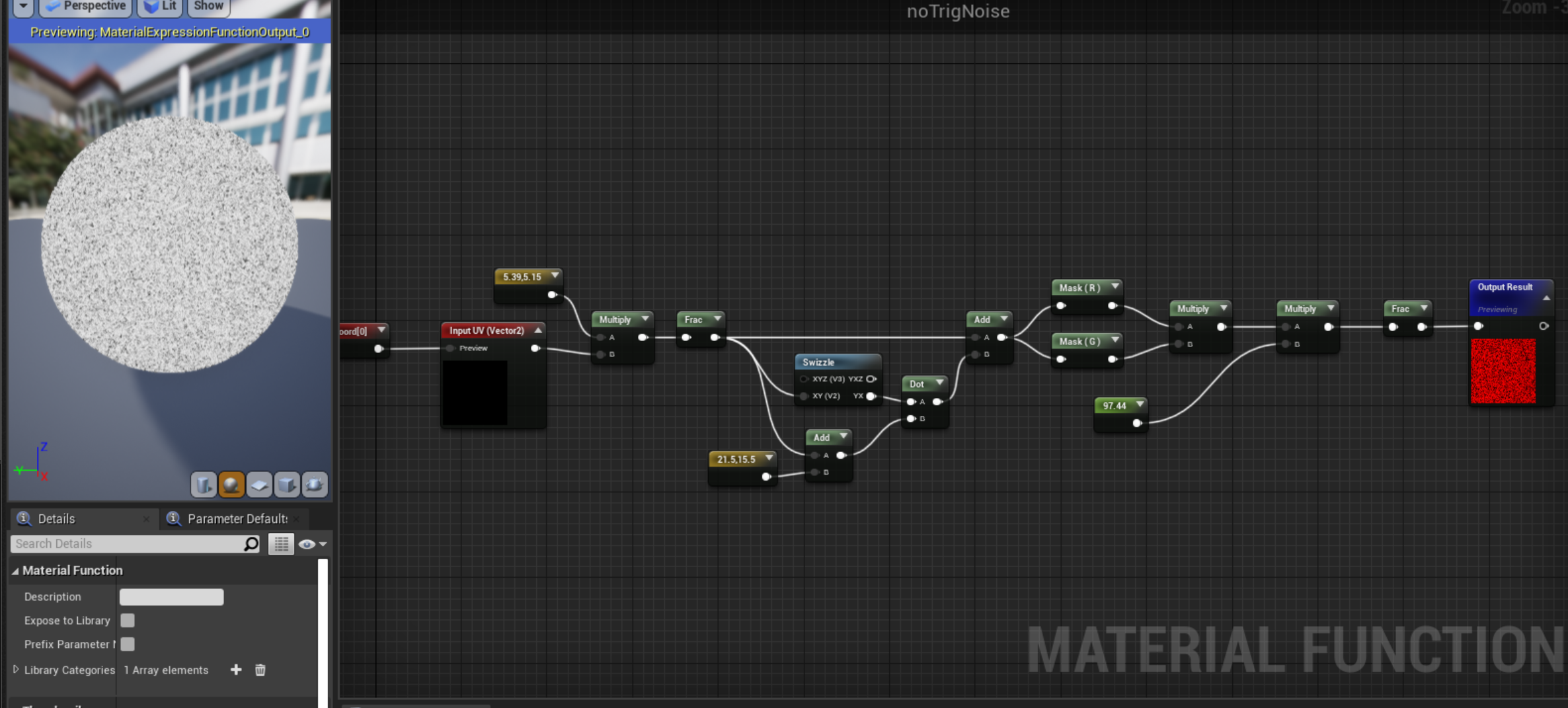
I need one other noise function for later.
This noise function I found it on a shadertoy and call it “no trig noise” because it uses no trigonometry to make the noise. I believe no trigonometry is better performance, but since I’ve never had to build any of these shaders not sure how much of a difference it makes.
FIRST LAYER: WIGGLY MAP
Now we’ve got our noise we can work on the first layer. I imported the texture that I made of the noise and I added a panner node so I could change the speed of the horizontal movement and I doubled the VTiling on the textCoord because I wanted to make it more wavy:
The tiling isn’t perfect and I messed a lot with the settings and couldn’t quite get the tiling to be on point for unreal, so if anyone knows how to do this let me know!
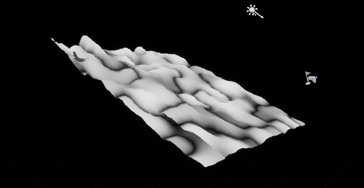
But we’ve got moving texture now we need to offset this to the world position.
Here’s a regular plane and here’s my high high poly plane next to each other so you can see what all those extra faces and vertices give you. Now looking at it with just the texture I have no idea what that artifacting is... doing the write up you find flaws you didn’t even know you had!
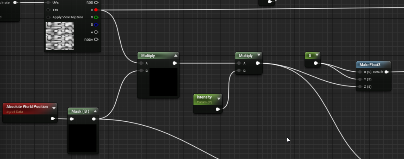
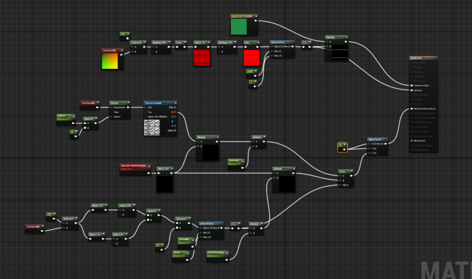
So I mask out the B (blue channel) of the world position because that’s the Up/Down axis in Unreal, in Unity it’s Y so G. I multiply that by just a channel of the texture because I don’t need all the RGB if I’m just using black/whites/and grays. Then I multiply that by an intensity so I can control the height. And then I combine everything into a float 3 and plug that into the world offset node of the material or the world displacement. I haven’t really seen a difference using either but then I didn’t see this artifacting before either so I might be missing something.
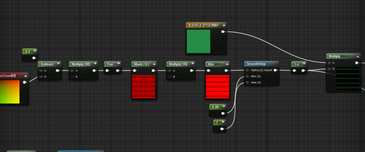
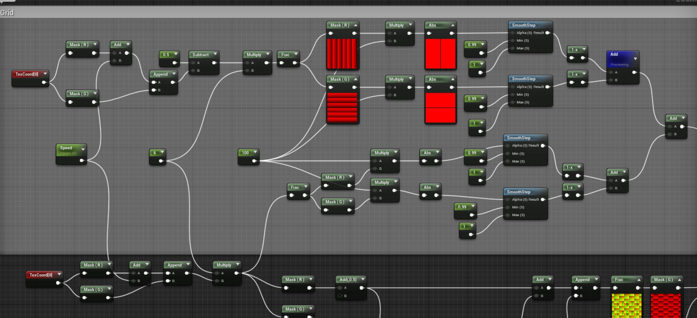
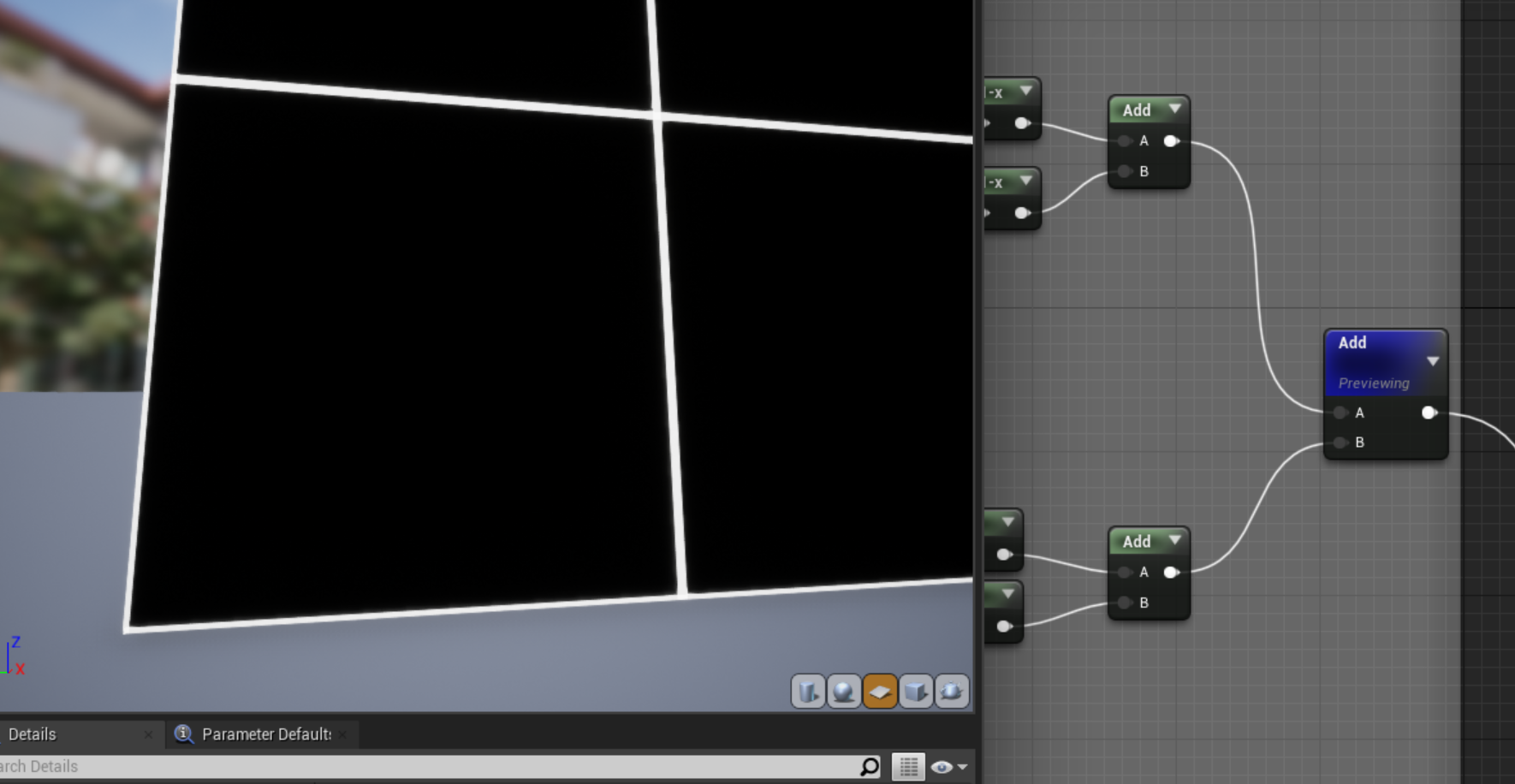
Then to make the lines I tile the UV, mask out the G channel, mutiply it to make it thinner, then absolute value it, smooth step that guy to make a solid line, and multiply by a final color and voila:
I plug the 1-x in the opacity and the multiply into the emissive and that gets me this:
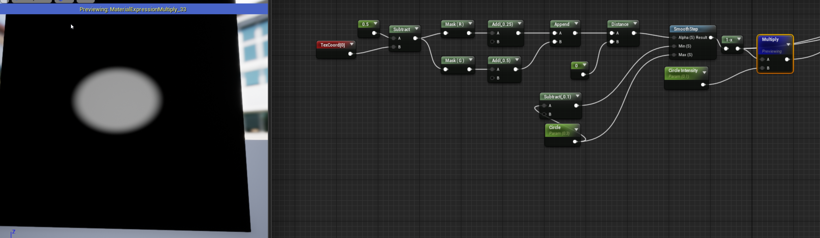
The final step would be to make a circle that I can control an explosion up and down in the middle. To do this we’re going to first make a circle and offset that to the world position:
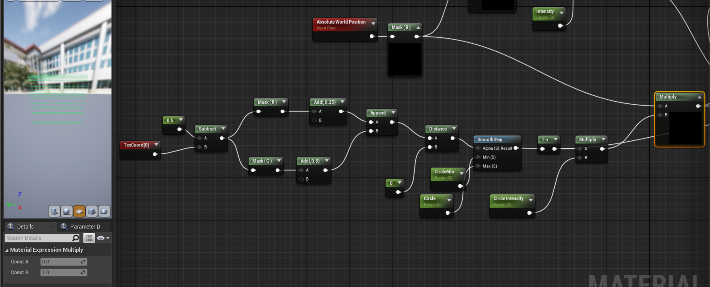
The channel masking and adding to the R/G channels is me putting the circle in the exact center since my mesh isn’t a square, the UVs are stretched a bit, and this is me countering that stretch. The distance and 0 nodes makes the circle shape, the smooth step defines it and I made the min/max parameters I can control. Then multiplying to the circle intensity will get you a height, and together just that plugged into the make float3 offset in the blue channel or Z in XYZ:
This is me playing around the the circle size (the max on the smoothstep) and the circle intensity (the multiplier)
Now to combine that with the squiggle noise offset made earlier you can add it but I found lerping it together made it a smoother transition so the circle blast would take over and then smooth out into the wiggles:
Add
Lerp
And that should be good for the first layer:

SECOND LAYER: GEOGRAPHY
The second layer is a duplicate of the first and then.... it all gets really messy. Since I’m not offsetting the world position to the object position (I didn’t realize that till I wrote this) the intensity of the vertex offset is quite intense when you just move the mesh up a bit...
Instead of actually fixing it I just knocked the intensity down to .1
Perfect... laziness always wins.
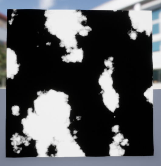
To do this layer I used the same noise but I wanted to knock out some areas to have “dark spots” where you could imagine a city is nested in the mountains. So to do this I had a similar setup but I used a second noise, this time just a node didn’t bother to make a render texture:
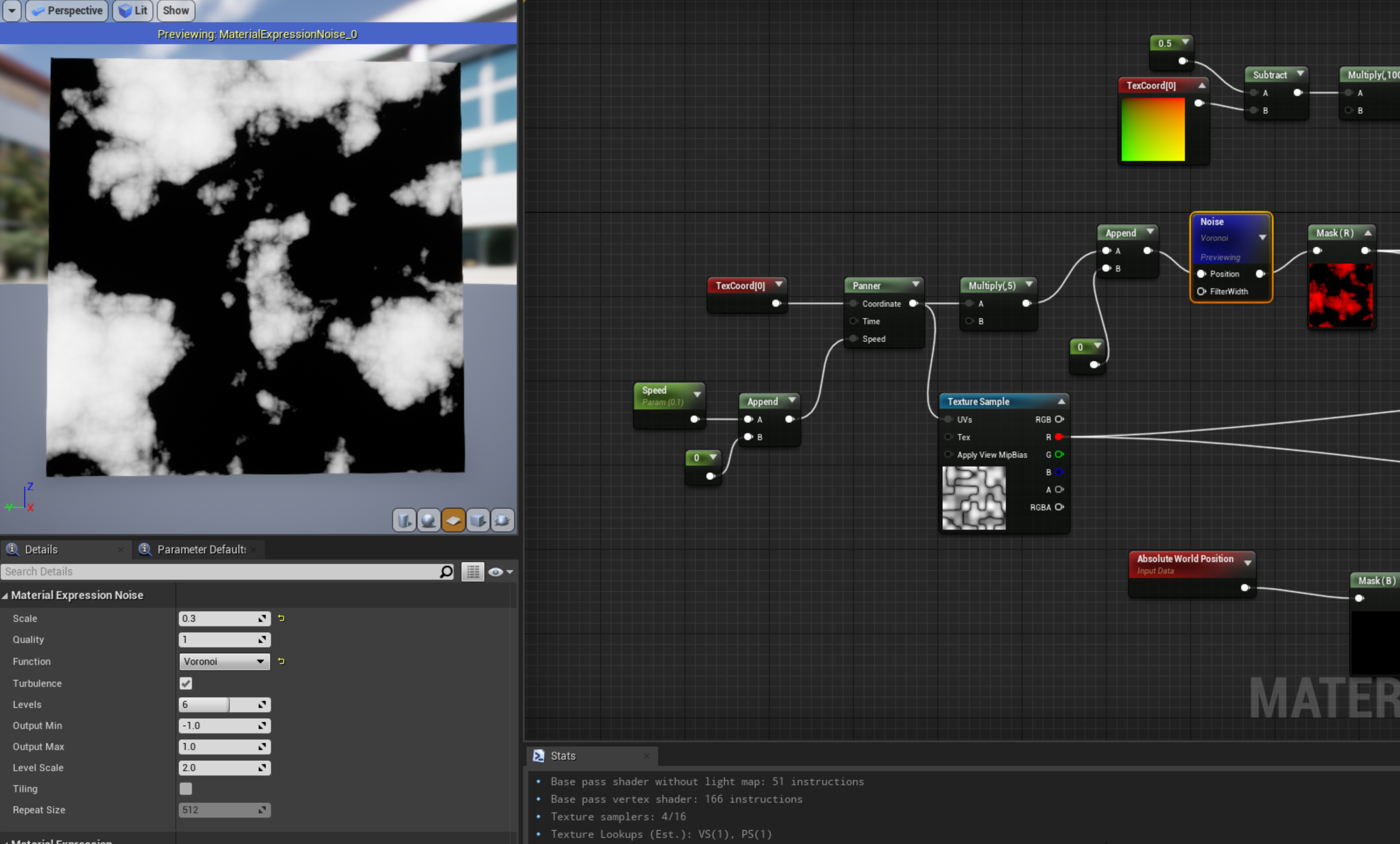
This Voronoi noise looked pretty good. I'm going to take those white spots and mask that out of the other texture and make those areas flat. So it’d look like:

Well... I see now my nodes are very messy but... I take the world position (blue channel) and multiply it both noise “textures” by that blue channel, and then subtract the Render Texture from the voronoi noise to knock out those white spots out of the original noise texture offset. So instead of rising up and down it should flatline wherever those white voronoi spots are. Then I smooth step because I wanted to trim a little more of the gray areas:
Raw Noise
Smoothstep
Not sure you ened this step but for me it just makes a crisper edge... you’ll see why soon once I can sort out my nodes... heh.
OK let’s go into why I’m going through this effort with masking out parts of our original noise to begin with. I want to make this little detail right here:
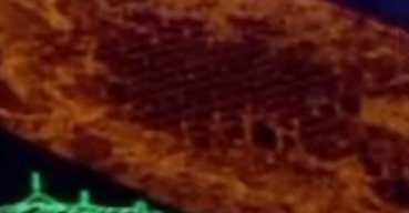
There’s the geography and then there’s these empty dark spaces that seem to have the same line grid we did before! So let’s make those grid lines first on those black spots we made. I probably did this out of order so I regret this decision but I swear my nodes are just as messy as my brain:

It’s the same technique as before to make the lines and I multiply a color and I lerp those lines with the smooth step I made for the voronoi noise. And when you plug that lerp node at the top into the emissive you should be getting what makes all that effort worth it?
We have sunken places check!
We have lines mapped to those sunken places check!
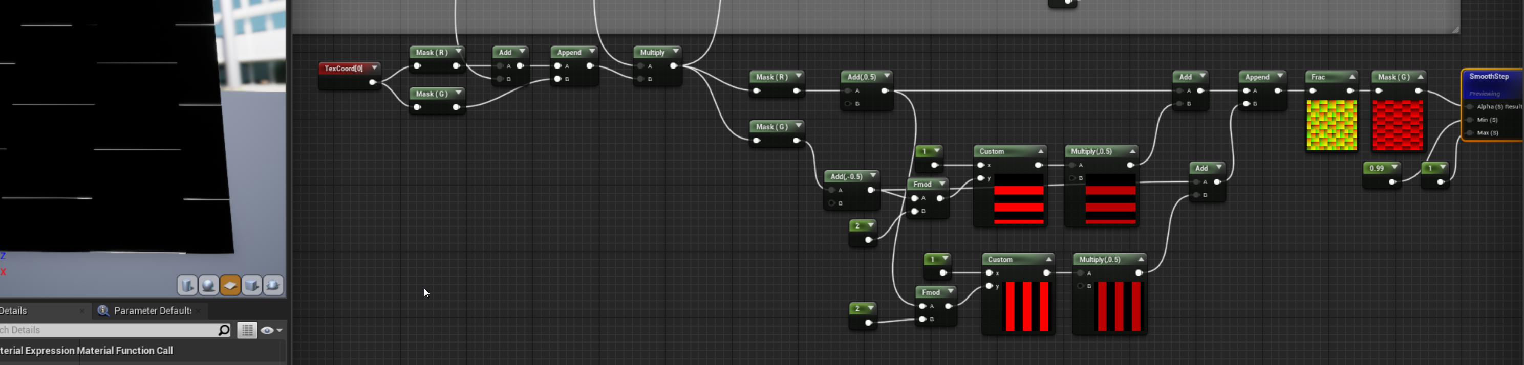
Ok now to make the geography shading or getting those mountain/hills definition. Since I already made some lines I thought why not make a grid to color the geography . Same technique as before but just you know add the Red channel.

Then just connect that to the lines made previously and you should get this:
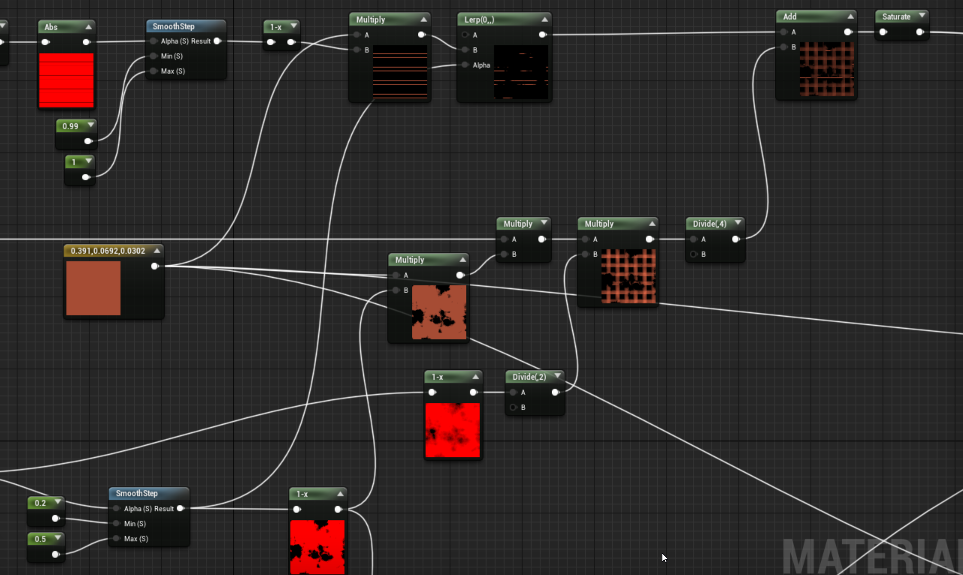
Now this section really confused me what kind of magic I did here. I’ll try to think back to my late night logic but it seems that I’m multiplying the smooth step noise AND the original voronoi noise (the one with with all the grays) to give it a more burnt look (with a million divides that can probably get consolidated one day), then I combine that with the grid, and run through a saturate node (this basically clamps the values to 0-1) and that’ll give you this look. Also if you plug that saturate node into the opacity AND emissive you get something that more resembles what my final output was:
We are almost through this mess... just have to get through the messiest part. The exploding circle!
Oh boy.
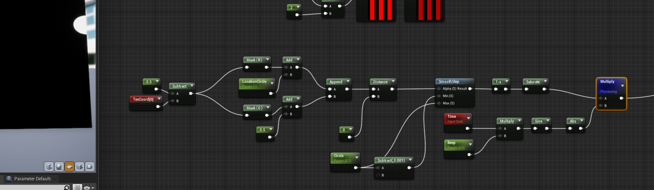
This is probably why my material is a hawt mess of nodes and I can’t seem to untangle it as much as I’ve spent more time trying to untangle these nodes than write this write up. The circle starts the same as the other so that part is easy:
Here I’m just subtracting .1 from the circle parameter as my minimum value for the smooth step since I want this to be a sharper circle no matter the size. You can multiply this to the world position (blue channel) and then unlike the first one where I lerped the different offsets together I thought add was much better:
Super simple... right? That multiply node is connected to the blue channel again from the world position. And what I’m not showing is I take the 1-x from the smooth step and multiply that to a color and add that to the lines/grid map we had before and then plug that into emissive and opacity.
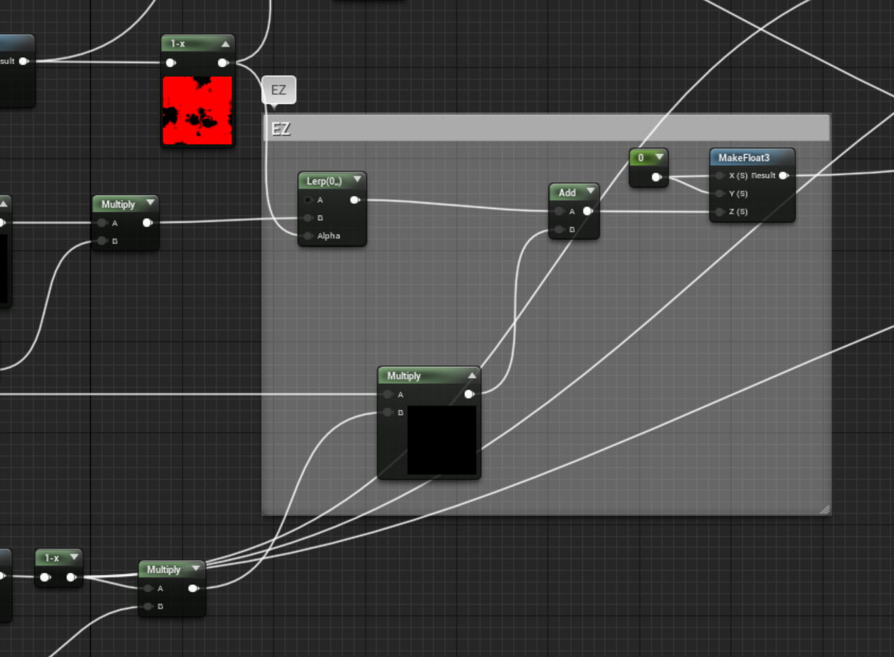
But that circle is only part of what I wanted, the next part is to make it look like there was static or interference going on with the “explosion” or whatever was happening. This is where that previous noise function comes in handy, so instead of multiplying to a color we’ll do a little bit more:
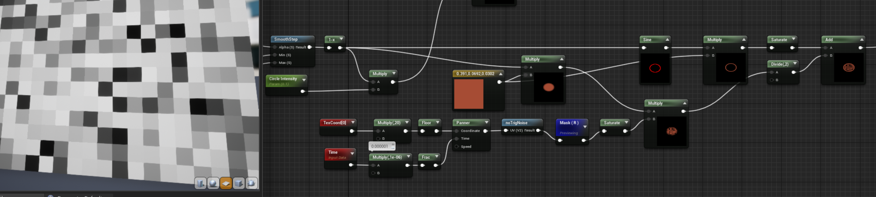
So using a UV with a floor in the “no Trig noise” function and adding a panner with a frac it’ll make the time a set framerate so instead of a smooth panner animation it will animate as if it were static? I’m not sure how to describe it but the gif will show soon.
Then I’m taking the circle and putting it through a sine, which makes a nice little border that we’ll add to the masked out circle static noise:
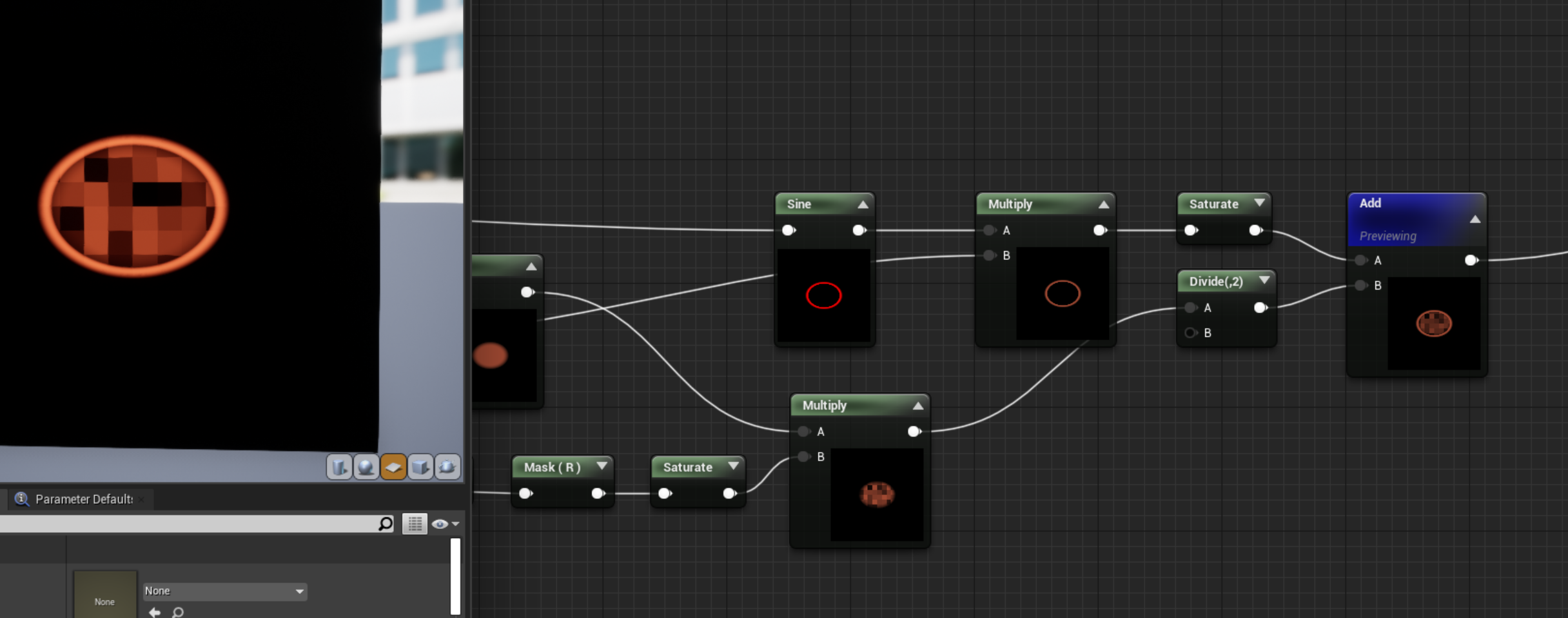
Add this to the lines/grid section and you should see this “static panner” animation with the pixels I was trying to describe. I promise it might be worth it?
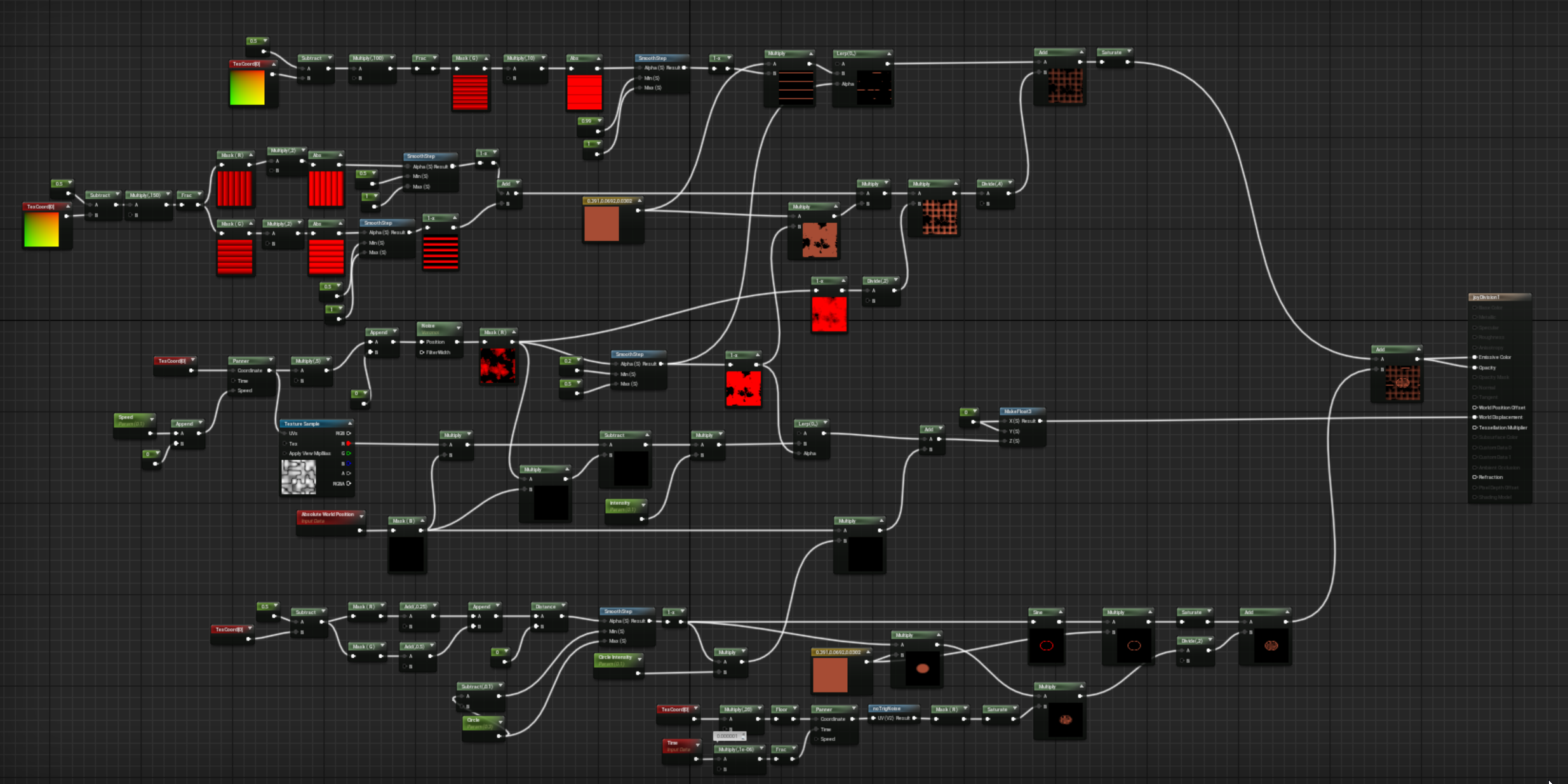
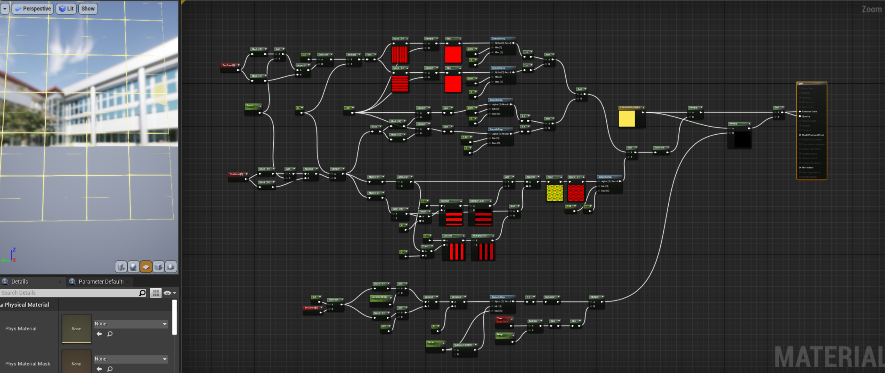
And that’s it! If you’ve managed to understand a fraction of the way my brain works that’s generally the process I went through for that material. Here’s my very unorganized thought process after trying to put some order into it.
And the final look:
THIRD LAYER: GRID
At this point the grid we’ve already made a version of it in the second layer, so it should be pretty easy from here.
So the one trick since my grid isn’t perfect there’s two sides of the mesh that won't have lines. So I duplicated the grid and set one pair of UVs normal and the other subtract by .5 and combined together:

Probably not the most efficient way of handling it but at this point I was ready to be done! Then to make the smaller part of the grid I took another page from the Book of Shaders using a fmod function to call the even rows and mask them out:
Then add that together and multiply a color, put both in opacity and emissive and you’ve got a grid!

And of course the last step is to add a circle! This one is special just because I added a sine animation to make it blink. I also added a bit more control of its UV positioning so I could animate the circle later
Multiplying that to the grid and plugging into emissive/opacity we’ve got our top layer.
PUTTING IT ALL TOGETHER
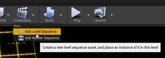
Animating wasn’t too bad. I added all the actors to the animation sequence and then found the spot where the parameters are hidden... in the StaticMeshCompontent0 under Element 0. Not as intuitive but wasn’t more than a few clicks away from finding it.

And the results are what you see: